Robot Actuator Specifications Explained: How to Read a Joint Module Datasheet
A joint module datasheet usually runs to more than twenty rows. The most common sizing mistakes come from treating similar parameters as the same thing: using peak torque as if it were continuous, reading encoder bits as positioning accuracy, or assuming a zero-backlash joint does not deflect under load. This guide sorts the datasheet into six parameter groups. For each group it explains the physics first, then reads the actual values of the EYOU PHU-17H-80 (reduction ratio 101), and finally shows how the numbers are used in actuator selection. All figures come from the product specifications and user manuals in the EYOU download center.
The Six Parameter Groups on a Datasheet
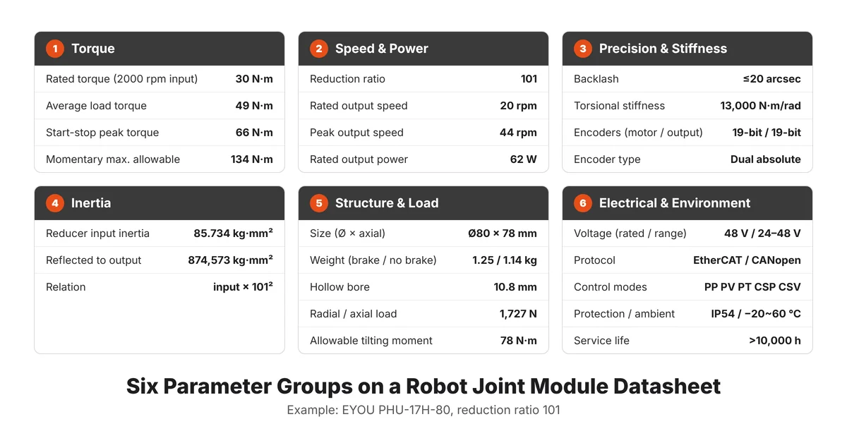
Row order varies between manufacturers, but every robot actuator datasheet can be read as six groups: torque; speed and power; precision and stiffness; inertia; structure and load; electrical, communication and environment. The first four decide whether the joint can perform the motion. The last two decide whether it fits the robot, connects to the control system and runs reliably over its service life. The figure below shows the full parameter set of the PHU-17H-80 (ratio 101); the sections that follow go through it group by group.
Torque: The Four Torque Ratings
Why torque is rated in levels
Torque is the turning moment about an axis, force multiplied by lever arm, in N·m. Two kinds of limits cap what a joint can deliver. The first is heat: copper loss in the motor winding rises with the square of current, so the torque available over long periods depends on keeping the winding below its insulation limit. The second is mechanical strength: the gear teeth, bearings and flexspline set how much short impact the reducer can survive, which caps peak and momentary torque. Peak torque is a sprint that lasts seconds; sustained output is governed by cooling, as Humanoid.guide explains in its analysis of peak vs continuous torque in humanoid joints. That is why datasheets split torque into levels by duration.
What the four values mean
The PHU-17H-80 (ratio 101) lists four torque values. The definitions below follow the glossary of the EYOU PHU & RHU user manual:
- Rated torque, 30 N·m (at 2000 rpm input): the load torque that may be applied continuously at the reducer output at the rated input speed of 2000 rpm.
- Average load torque at output, 49 N·m: the upper limit for the average load torque over a duty cycle with varying load or speed. Exceeding it over time degrades the lubricant early and accelerates tooth wear.
- Start-stop peak torque at output, 66 N·m: the maximum torque the joint can withstand during start-up, stopping or short overloads.
- Momentary maximum allowable external torque, 134 N·m: the maximum short, unexpected external impact the reducer can survive, such as a collision. The manual states that applied torque must never exceed it; doing so can loosen screws, cause play or damage the structure.
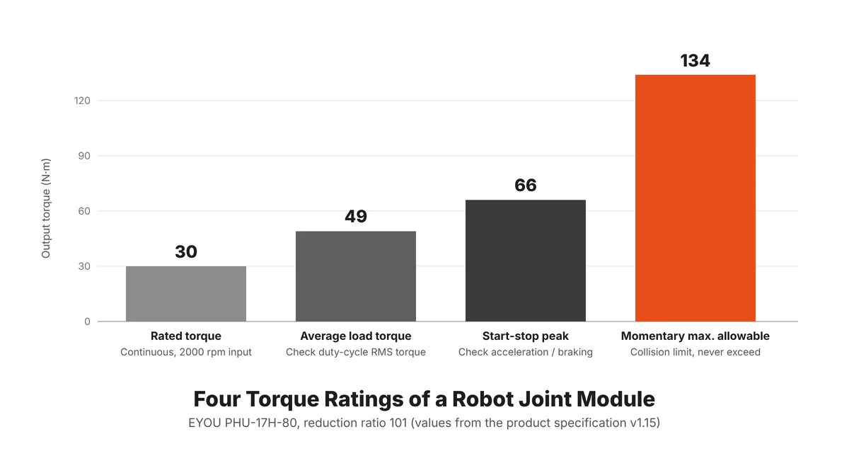
The same table lists the internal motor: 0.6 N·m rated and 1.8 N·m peak. Multiplied by the ratio of 101, that gives about 61 N·m and 182 N·m, well above the joint's 30 N·m rated and 66 N·m start-stop peak. Joint torque ratings are set by reducer life and strength, which is what the "life constraint" label on the datasheet indicates. Estimating joint capability as motor torque × ratio overstates what the joint can carry over its service life.
How to use them in sizing
Split one complete motion cycle into time segments, calculate the output torque each segment needs, and check it at three levels:
- The RMS torque of the duty cycle against the average load torque.
- The highest torque during acceleration and braking against the start-stop peak torque.
- Collisions and emergency stops against the momentary maximum allowable torque. This level is a safety ceiling; normal operation should never reach it.
RMS torque is calculated as:
Trms = √Σ Ti2 tiΣ ti
where Ti is the torque in segment i and ti its duration.
Joints that hold a static pose for long periods need a separate check. At zero speed all electrical input turns into heat, so the winding warms fastest. PHU joints are available with a brake (B): once the servo is disabled, the brake locks the output and holds the load with no current in the winding. For the link between continuous torque and temperature, see Robot Actuator Cooling: The Four Stages of Thermal Management; for the cubic relationship between average load torque and harmonic reducer life, see Harmonic Drive Systems Explained.
Speed, Reduction Ratio and Power
How the ratio trades speed for torque
A reducer with ratio i divides motor speed by i and multiplies torque by roughly i, minus transmission losses. Power is torque multiplied by angular velocity; with speed n in rpm:
P = T × ω = T × 2πn60
Joints of one frame size are often offered in two or more ratios. The PHU-17H-80 comes in ratio 51 and ratio 101:
| Parameter | Ratio 51 | Ratio 101 |
|---|---|---|
| Rated torque (2000 rpm input) | 19.8 N·m | 30 N·m |
| Average load torque | 32 N·m | 49 N·m |
| Start-stop peak torque | 42 N·m | 66 N·m |
| Rated output speed (life constraint) | 39 rpm | 20 rpm |
| Peak output speed | 88 rpm | 44 rpm |
| Rated joint output power (life constraint) | 81 W | 62 W |
Reading the table: torque, speed and power should agree
The rated speed of 20 rpm at ratio 101 matches 2000 rpm input ÷ 101 ≈ 19.8 rpm. Check the power: 30 N·m × 2π × 20 ÷ 60 ≈ 62.8 W, consistent with the listed 62 W. The same check works on any datasheet; when the three values agree, they were rated under the same condition. "Life constraint" means the joint reaches its rated service life when run continuously at that speed. Peak speed is for short moves.
In sizing: choose the ratio by speed, then check torque
Example: a joint must rotate 90° in 0.5 s. The average speed is 180°/s, or 30 rpm. With a trapezoidal profile that spends one third of the time accelerating and one third braking, the top speed is about 45 rpm. That exceeds the 44 rpm peak of the ratio-101 version, so ratio 51 is the right starting point, and the load is then checked against the ratio-51 torque values. If ratio 51 is short on torque, the next step is a larger frame size.
Precision and Stiffness: Backlash, Torsional Stiffness and Encoders
Backlash: lost motion at reversal
Backlash is the clearance between meshing gear teeth. When the input reverses, the output does not move until the input has crossed that gap; the lost angle is the backlash, given in arc-seconds (″) or arc-minutes (′), with 1° = 60′ = 3600″. In a harmonic reducer the teeth stay fully engaged in the mesh zone, so there is essentially no flank clearance; the backlash figure on the datasheet is measured as hysteresis and describes lost motion near zero torque.
The PHU-17H-80 is rated at ≤20″ backlash; the EYOU RP planetary joint at 15′ (900″). To convert to position error at the end of an arm, multiply the backlash angle in radians by the arm length. On a 0.5 m arm, 20″ is about 0.05 mm and 15′ about 2.2 mm. Fine-manipulation positions such as wrists, hands and the distal axes of a collaborative arm should be selected on backlash first. Impact-loaded positions such as humanoid legs can accept more backlash in exchange for the shock tolerance of planetary gearing.
Torsional stiffness: zero backlash still twists
Torsional stiffness is the torque required to twist the output by one radian, in N·m/rad. Under torque T, the elastic wind-up at the output is:
θ = TK
The PHU-17H-80 reducer has a torsional stiffness of 13,000 N·m/rad. At the rated 30 N·m, θ ≈ 0.0023 rad, about 7.9′, more than 20 times the backlash figure; on a 0.5 m arm that is roughly 1.15 mm of deflection at the end. The flexspline of a harmonic reducer is an elastic part by design, so it winds up under load; Humanoid.guide covers this in Backlash and Torsional Stiffness in Humanoid Joints. Real harmonic stiffness is softer at low torque and stiffens as torque rises, so the single value on a datasheet is best used for estimates.
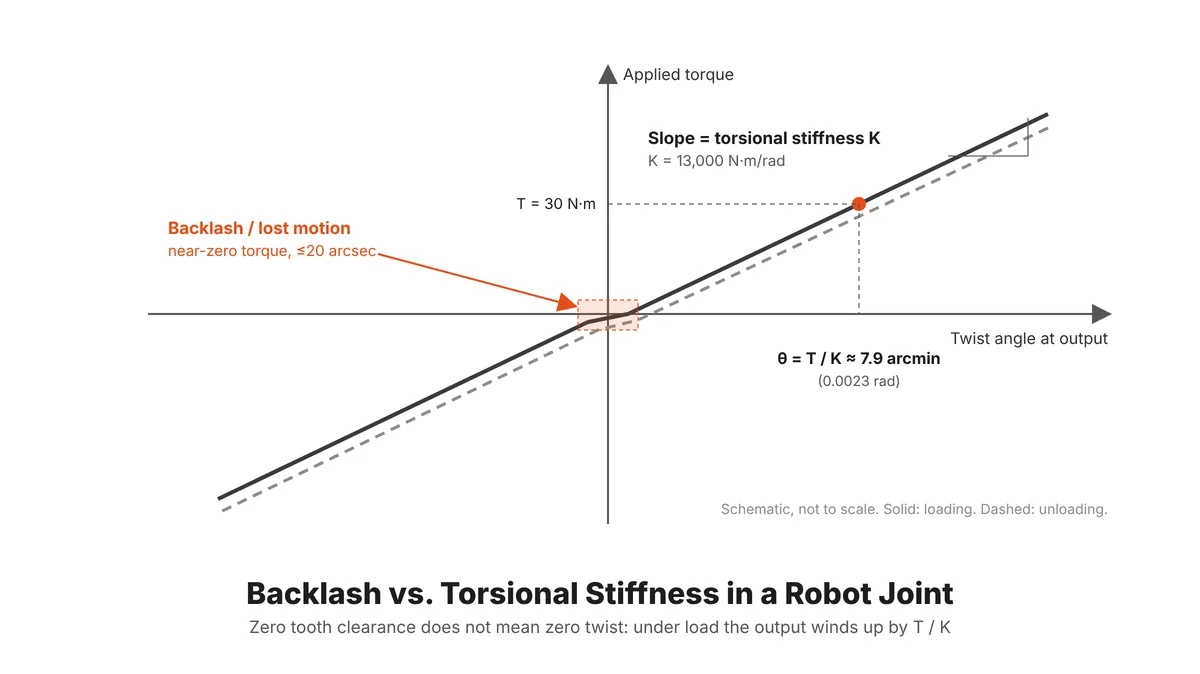
Joints with large load changes and tight path accuracy requirements should be selected on backlash and stiffness together. Stiffness also sets the resonant frequency of the joint-plus-load system, which limits how high the position loop bandwidth can be tuned. EYOU harmonic joints carry an encoder at the reducer output that measures the true load-side angle, so wind-up is detected and corrected in the position loop.
Encoders: bits describe resolution
An encoder with n bits divides one revolution into 2n counts. Resolution is the smallest angle it can distinguish; accuracy is how far the reading is from the true position, which also depends on mounting eccentricity, signal noise and calibration. An absolute encoder keeps its position through power loss and needs no homing after restart.
The PHU-17H-80 uses dual absolute encoders, 19-bit on the motor side and 19-bit on the reducer side. 19 bits means 524,288 counts per revolution, about 2.47″ per count. The motor-side encoder sits before the reducer, so its resolution at the output is further divided by the ratio. The bit count on a datasheet sets the ceiling on control resolution; final positioning accuracy still depends on backlash, stiffness and calibration.
Inertia: How the Reduction Ratio Changes What the Motor Feels
Moment of inertia and reflection through a gear
Moment of inertia J describes resistance to angular acceleration, in kg·m², with T = J·α. Through a reducer of ratio i, inertias must be referred to the same shaft before they can be compared: motor-side inertia reflected to the output is multiplied by i², and load inertia reflected to the motor is divided by i² (see Motion Control Tips on how gearmotors affect reflected inertia).
Jout = Jin × i2 Jref = Jloadi2
Reading the table
The PHU-17H-80 lists a reducer input inertia of 85.734 kg·mm² and a reflected output inertia of 874,573 kg·mm², which is exactly 85.734 × 101². That is about 0.87 kg·m², the same as a 5 kg mass at a 0.42 m radius. The ratio-51 version lists 222,994 kg·mm² (about 0.22 kg·m²), roughly a quarter of the ratio-101 value.
In sizing
When calculating acceleration torque, add the joint's own reflected inertia to the load inertia:
Tacc = (Jload + Jjoint) × α
Counting only the load underestimates the torque needed to accelerate, and the error grows with the ratio. A second check is the inertia ratio: load inertia divided by the joint's reflected inertia. A ratio near 1 gives efficient acceleration and makes stable tuning easier; a large ratio lets load changes disturb control noticeably. High-ratio joints also present a large reflected inertia when pushed from the output side, which matters where passive compliance or soft collision behavior is required.
Structure and Load: Dimensions, Weight and Output Bearing Capacity
Three loads on the output bearing
The output bearing of a joint carries radial force, axial force and tilting moment at the same time. Tilting moment comes from loads that act off the bearing center: the further a cantilevered link places its load from the bearing, the larger the moment. Most joints in robot arms and humanoids are loaded as cantilevers, so the moment limit is often reached before the torque limit.
Reading the table
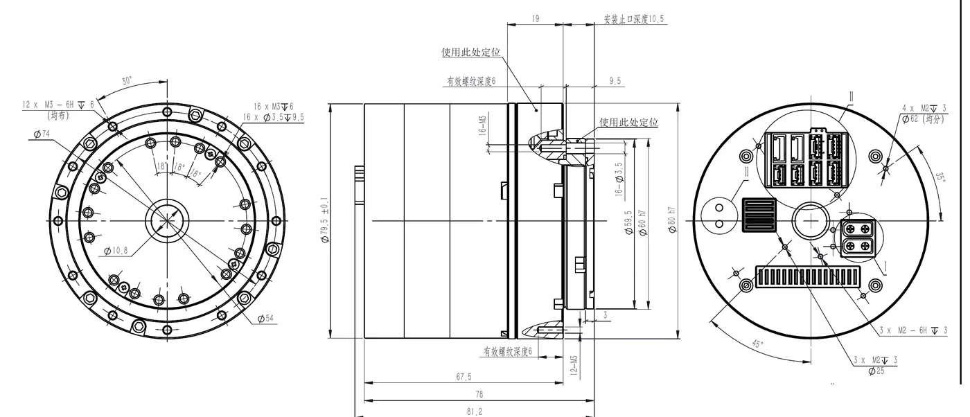
The PHU-17H-80 measures Ø80 mm × 78 mm axial and weighs 1.25 kg with brake or 1.14 kg without, with a 10.8 mm hollow bore. Allowable radial and axial loads at the output are both 1,727 N, and the allowable tilting moment is 78 N·m.
In sizing
Check the moment with M = Fr×(Lr+R) + Fa×La; the symbols are explained in Harmonic Drive Systems Explained. The hollow bore decides whether cables can pass through the joint center, so for internally routed multi-axis mechanisms, confirm the harness diameter first. Joint weight is also load on the joints upstream: each extra 1 kg at a forearm joint 0.3 m from the shoulder adds about 2.9 N·m of gravity torque at the shoulder. For the engineering routes to lighter joints, see How to Improve Robot Actuator Power Density.
Electrical, Communication and Control Modes
What the parameters mean
Rated voltage is the voltage at which the datasheet performance was measured; the operating range is the window in which the joint runs. Below rated voltage, motor back-EMF limits the achievable top speed, so peak speed usually drops. The communication protocol defines how the joint exchanges data with the host controller. Control modes follow the CiA 402 drive profile: in the profile modes (PP, PV, PT) the drive plans the trajectory itself from a target value; in the cyclic synchronous modes (CSP, CSV) the master sends a new target every communication cycle, which suits synchronized multi-axis motion. STO (Safe Torque Off) removes motor torque through a hardware signal for emergency-stop functions.
Reading the table
The PHU-17H-80 is rated at 48 VDC with a 24–48 VDC operating range and a built-in drive. Its interfaces are power, CAN FD, EtherCAT and STO. The same frame supports both EtherCAT and CANopen, switchable in software. Control modes include PP, PV, PT, CSP and CSV.
In sizing
Robots with many synchronized joints, such as humanoids and collaborative arms, generally run EtherCAT in CSP mode; single-axis point-to-point devices or machines with few joints work well with CANopen in PP mode. The power supply design must handle regenerated energy: during fast braking the motor acts as a generator and raises the bus voltage, and above the overvoltage threshold (60 V in the manual's example) the drive faults and stops, so energy recovery must be configured as the manual describes. For protocol differences, see Robot Communication Protocols: CAN, CANopen, CAN FD, and EtherCAT.
Environment and Service Life
What the parameters mean
IP ratings are defined by IEC 60529. The first digit covers solid particles; 5 means dust-protected (some dust may enter but not enough to affect operation). The second digit covers water; 4 means protection against splashing from any direction. Housing temperature rise is how far the housing runs above ambient. Service life is given in hours and corresponds to the rated torque and rated speed marked "life constraint".
Reading the table
The PHU-17H-80 operates from −20 to 60 °C ambient, with housing temperature rise ≤60 °C, noise ≤60 dB, IP54 protection and a service life above 10,000 h.
In sizing
IP54 suits indoor and general industrial environments; washdown, rain or immersion requires additional external protection. Per the manual's inspection criteria, housing temperature normally stays within ambient + 60 °C, so positions with frequent human contact should be guarded against burns. Service life is stated at rated conditions and increases when the actual load is lower; the estimation method is covered in Harmonic Drive Systems Explained.
A Worked Selection Check
The example below runs through the full checking sequence. The load case is an assumed demonstration case.
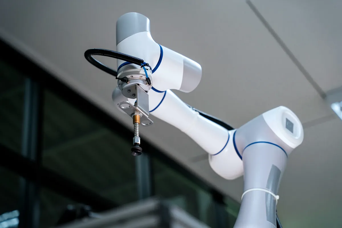
Example: the elbow joint of a collaborative arm carries a 5 kg payload 0.5 m from the joint axis. The link weighs 2 kg, is 0.5 m long and has uniform mass. The joint must turn 90° in 1 s on a trapezoidal profile, with one third of the time accelerating and one third braking. Worst case, with the link horizontal throughout:
- Gravity torque: (5 × 0.5 + 2 × 0.25) × 9.81 ≈ 29.4 N·m
- Load inertia: 5 × 0.5² + 2 × 0.5² ÷ 3 ≈ 1.42 kg·m²
- Top speed: 90° ÷ 1 s × 1.5 = 135°/s ≈ 22.5 rpm; angular acceleration ≈ 7.1 rad/s²
- Acceleration torque, including the joint's own 0.87 kg·m² reflected inertia: (1.42 + 0.87) × 7.1 ≈ 16.2 N·m
- Segment torques: about 45.6 N·m accelerating, 29.4 N·m at constant speed, about 13.2 N·m braking; RMS torque ≈ 32.3 N·m
| Check | Requirement | PHU-17H-80, ratio 51 | PHU-17H-80, ratio 101 |
|---|---|---|---|
| RMS torque vs. average load torque | 32.3 N·m | 32 N·m, fails | 49 N·m, passes |
| Peak torque vs. start-stop peak | 45.6 N·m | 42 N·m, fails | 66 N·m, passes |
| Top speed vs. peak output speed | 22.5 rpm | 88 rpm, passes | 44 rpm, passes |
| Inertia ratio (load ÷ joint reflected) | — | ≈ 6.4 | ≈ 1.6 |
| Radial force vs. allowable radial load | 68.7 N | 1,727 N, passes | 1,727 N, passes |
| Tilting moment vs. allowable moment (resultant assumed 0.05 m from bearing center) | 3.4 N·m | 78 N·m, passes | 78 N·m, passes |
| Collision ceiling | Safety limit | 86 N·m | 134 N·m |
Result: ratio 101 passes every check, with about 34% margin on RMS torque, 31% on peak torque and an inertia ratio of about 1.6; ratio 51 is short on torque. A real selection adds a safety factor and accounts for posture changes, end tooling and cable loads. Our application engineers can review your load case if you send the data.
Key Parameters Across EYOU Joint Series
| Series | Reducer | Outer diameter | Peak torque range | Encoder | Protocol | Typical positions |
|---|---|---|---|---|---|---|
| PHU enhanced harmonic actuator | Harmonic | Ø40–170 mm | 2.3–800 N·m | Dual absolute, 19-bit | EtherCAT / CANopen | Collaborative arms, humanoid upper body, industrial automation |
| RHU humanoid harmonic actuator | Harmonic | Ø52–130 mm | 12–800 N·m | Dual absolute | EtherCAT / CANopen | High-precision humanoid positions |
| PHA lightweight harmonic actuator | Harmonic | Ø43–80 mm | 3.3–66 N·m | Dual absolute, 16-bit | CANopen | Weight-sensitive light-load joints |
| RP humanoid planetary actuator | Planetary | Ø45–96.5 mm | 6–120 N·m | Inductive absolute, 17-bit in / 19-bit out | CANopen / CAN FD | Humanoid legs |
| PP planetary actuator | Planetary | Ø32–52 mm | 0.48–18 N·m | Dual absolute, 16-bit | CANopen | Compact light-load joints |
Note: harmonic series list start-stop peak torque; planetary series list peak torque. Full parameters for each model are in the latest specifications available for download on our website.
In short, read a datasheet in this order: fix the ratio from the speed requirement; check RMS, peak and momentary torque level by level; then inertia, moment and mounting dimensions; and finally voltage, protocol and environment. The EYOU PHU, RHU and PHA harmonic joints and RP planetary joints all come with full specifications and user manuals for download. You can also send the joint position, load and motion requirements to our application engineers for a model recommendation.
FAQ
Rated torque is what the joint can deliver continuously at rated speed, limited by winding temperature and reducer life. Peak torque is the maximum it can withstand during start-up, stopping or short overloads, and only for short periods. In sizing, compare the duty-cycle RMS torque with the average load torque, and the highest acceleration torque with the start-stop peak torque. For the EYOU PHU-17H-80 (ratio 101), rated torque is 30 N·m, average load torque 49 N·m and start-stop peak torque 66 N·m.
It is the maximum short, unexpected external impact torque the reducer can survive, such as a collision or emergency stop. It is a protective ceiling that a normal duty cycle should never use. Exceeding it can loosen screws, create play or damage the structure. For the PHU-17H-80 (ratio 101) the value is 134 N·m.
No. Backlash only describes lost motion near zero torque. Under load the reducer and structure twist elastically, by roughly torque divided by torsional stiffness. With 13,000 N·m/rad, the PHU-17H-80 winds up about 7.9 arc-minutes at 30 N·m, more than 20 times its ≤20 arc-second backlash. An output-side encoder measures this deflection so the position loop can correct it.
Bit count sets resolution, the smallest angle the encoder can distinguish: a 19-bit encoder gives 524,288 counts per revolution, about 2.47 arc-seconds. Positioning accuracy also depends on backlash, torsional stiffness, mounting and calibration. High resolution is one condition for high accuracy; on its own it does not define accuracy.
Add two parts. Gravity torque is each mass times gravitational acceleration times its horizontal distance from the joint axis, highest when the link is horizontal. Acceleration torque is the load inertia plus the joint's own reflected inertia, times angular acceleration. Split one motion cycle into segments, compare the RMS torque with the average load torque and the highest torque with the start-stop peak torque, then add a safety factor.
A reducer of ratio i divides speed by i, and equating kinetic energy scales inertia by i²: load inertia reflected to the motor is divided by i², and motor-side inertia reflected to the output is multiplied by i². A higher ratio reduces the load's influence on the motor but increases the joint's own inertia seen at the output. The PHU-17H-80 has 85.734 kg·mm² of reducer input inertia, which becomes 874,573 kg·mm² at the output with ratio 101.
Under IEC 60529, 5 means dust-protected (limited dust ingress that does not affect operation) and 4 means protected against splashing water from any direction. IP54 suits indoor and general industrial environments; washdown, rain or immersion needs additional external protection.