Robot Communication Protocols: CAN, CANopen, CAN FD, and EtherCAT
For a robot to move, the controller must continuously tell every joint where to go and how hard to push, and every joint must continuously report its state back. This communication system works like the robot's nervous system, connecting the "brain" (the controller) to the "body" (joints, sensors, and other actuating and sensing parts). At its core is a standardized set of rules — the communication protocol — that defines how data travels, what it means, and who goes first, so that devices from different sources can understand each other and work together.
Four protocols dominate robot joint communication: CAN, CANopen, CAN FD, and EtherCAT. They are not simple rivals — CAN is the hardware foundation, CANopen and CAN FD are both built on top of it, and EtherCAT takes the Ethernet route. This article walks through each layer in that order: what it is, how it works, and how it differs from the others.
What Is a Communication Protocol?
A communication protocol is three agreements in one: how data is transmitted (electrical signaling and frame format), what the data means (application-layer semantics), and who transmits first (arbitration and timing). On a robot, the protocol directly determines three performance figures: command latency (real-time behavior), multi-axis synchronization accuracy, and how many joints a single bus can carry. There is no universally best protocol — only the best fit for a given requirement.
CAN: The Four-Decade Hardware Foundation
CAN is a fundamental hardware communication protocol, and its defining feature is non-destructive bitwise arbitration. In plain terms, when several devices compete for the bus at the same moment, this mechanism automatically ranks every message by priority: the highest-priority message passes through undisturbed, and lower-priority ones yield. This deterministic preemption means critical commands — such as an emergency stop — are always executed first. It is the root reason CAN has survived forty years in automotive and robotics without being displaced.
On reliability, CAN carries multiple layers of error detection and correction, including CRC checking and bit-error detection, so transmission anomalies are identified and handled. Its differential signaling resists electromagnetic interference, which suits it to environments dense with strong interference sources such as motors and drives.
Two engineering limits are worth remembering: a single frame carries at most 8 bytes of data, and the maximum bit rate is 1 Mbit/s — at which the bus can be no longer than roughly 40 meters. Typical CAN applications include on-board component communication inside robots, automotive electronics, and small to mid-sized automation equipment.
CANopen: A Common Working Language for Joints
CANopen is a standardized application-layer protocol (the CiA 301 specification) built on CAN hardware — a common "working language" for joint communication. Through its object dictionary, every parameter (position, velocity, control word) receives a uniform address — a 16-bit index plus an 8-bit sub-index — so devices from different manufacturers can interpret each other's data.
On the communication side, CANopen defines four complementary mechanisms: PDO for real-time process data, SDO for parameter configuration, NMT for node lifecycle management, and SYNC for multi-axis synchronization triggers. Together they balance real-time transmission with configuration flexibility.
The NMT State Machine: A Node's Lifecycle
Every CANopen node is governed by a network management state machine:
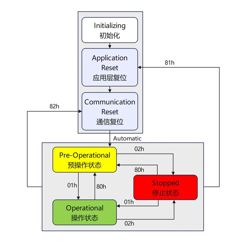
After power-up, the node enters Initializing; once self-checks and the application and communication resets complete, it automatically moves to Pre-Operational — SDO configuration is possible here, but PDO real-time communication is not yet active. A start command (01h) from the master brings the node to Operational, where all communication functions are live; a stop command (02h) returns it to Stopped, where only basic communication remains. Two further commands — reset node (81h) and reset communication (82h) — cover fault recovery. This state machine lets the master start, stop, and reset every joint on the bus in a uniform way.
PDO Configuration: Disable, Map, Then Enable
A PDO is not ready out of the box — it must be mapped first:
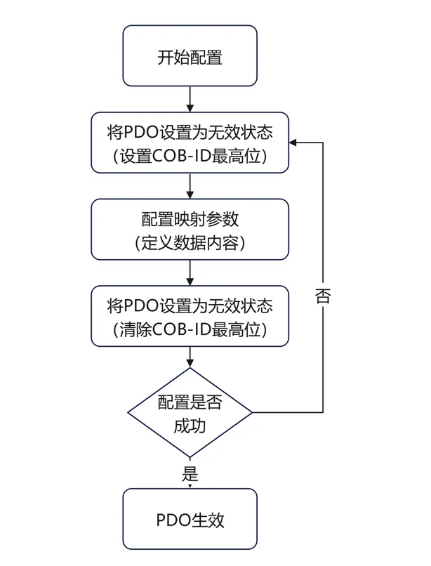
The PDO is first set invalid (by setting the highest bit of its COB-ID); mapping parameters are then written to define which object dictionary entries the frame carries; the highest bit is cleared to make the PDO valid; and finally the configuration is verified — if the check fails, the process repeats. This sequence guarantees that no half-configured frame ever appears on the bus.
Heartbeat and Node Guarding: Monitoring Who Is Online
With a dozen joints on one bus, how do you notice when one drops offline? CANopen offers two complementary mechanisms:
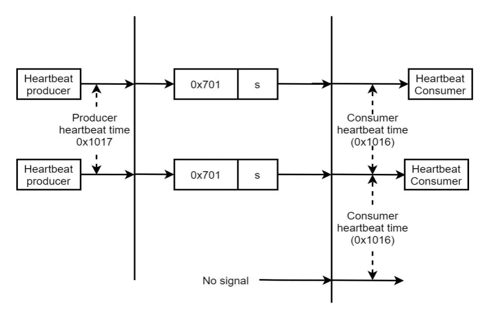
Heartbeat is node-initiated reporting: the joint (producer) periodically emits a status frame with COB-ID 0x700 + node ID, at the interval set in object 0x1017. If the master (consumer) receives nothing within its consumer heartbeat time (object 0x1016), the node is judged abnormal.
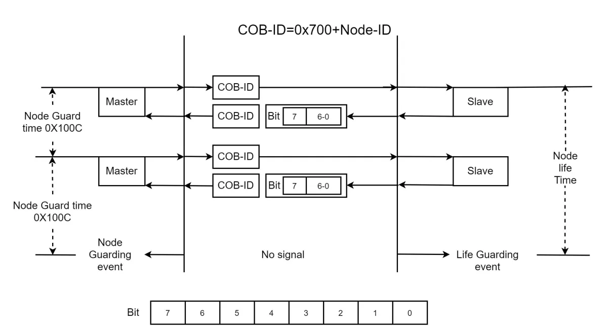
Node guarding is master-initiated roll call: the master polls each slave at the node guard time (object 0x100C), and the slave answers with one status byte (Bit 7 is a toggle bit, Bits 6-0 carry the node state). A missing reply within the lifetime triggers a guarding event. The two mechanisms — slave-initiated and master-initiated — can run simultaneously.
This system makes CANopen one of the most mature foundations for modular, low-cost, interchangeable joint communication. However, constrained by the bandwidth and synchronization of the underlying CAN bus, CANopen has a clear ceiling in multi-axis synchronization accuracy and overall throughput — a bus carries at most 127 nodes, all sharing 1 Mbit/s. It therefore fits small multi-joint robots and simple service robots with modest performance demands.
CAN FD: A Bandwidth Upgrade for CAN
CAN FD (Flexible Data-Rate) is a CAN extension released by Bosch in 2012 and standardized in ISO 11898-1 in 2015. Its upgrades come in three parts. First, the maximum payload grows from 8 bytes to 64 bytes, reducing frame splitting for larger data and improving efficiency. Second, CRC checking is strengthened from 15 bits to 21 bits, preserving data integrity on long frames. Third, a dual bit-rate mechanism keeps the arbitration phase at the classic rate (up to 1 Mbit/s) for compatibility while the data phase switches to a higher speed — commonly 5 Mbit/s in practice — balancing reliability against latency.
One compatibility caveat: a CAN FD node can send and receive classic CAN frames, but a classic CAN node will raise an error when it sees a CAN FD frame. When the two node types share a bus, the FD nodes must operate in classic CAN mode — 8-byte frames at no more than 1 Mbit/s.
Compared with EtherCAT, CAN FD hardware is cheaper and development is simpler; EtherCAT, in turn, achieves microsecond-level multi-axis synchronization, where CAN FD is weaker. CAN FD therefore suits robots with many joints but non-extreme synchronization demands — collaborative robots and some lightweight humanoids, for example — where it meets performance needs at a significantly lower system cost.
EtherCAT: Built for Synchronization Accuracy
EtherCAT is a real-time Ethernet protocol introduced by Beckhoff in 2003 and later standardized as IEC 61158. It is the mainstream choice in high-performance robotics.
Processing on the Fly: One Frame Serves the Whole Bus
The core mechanism of EtherCAT is processing on the fly:
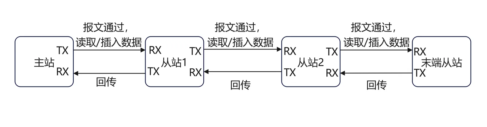
A frame sent by the master travels through every slave in turn. As it streams past, each slave controller reads its own output data and inserts its input data directly from the moving frame; the remainder continues downstream until the last slave returns the frame to the master. All of this is done by dedicated slave hardware (the ESC) with virtually no processing delay — a single frame completes the data exchange for the entire bus. That is the foundation of EtherCAT's real-time performance.
Distributed Clocks: Every Joint Acts in the Same Microsecond
Distributed clocks give every slave a local clock and automatically compensate clock offsets and propagation delays between stations:
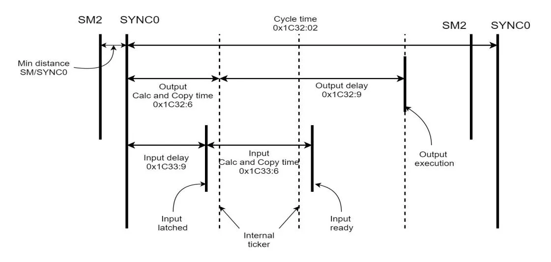
The diagram shows one full cycle: after the SYNC0 trigger, the slave executes its output at an exact instant defined by the output calc-and-copy time (0x1C32:6) and output delay (0x1C32:9); on the input side, sampling is latched according to the input delay (0x1C33:9). Through this mechanism, all slave devices — joints, sensors, and so on — act within the same microsecond, with synchronization jitter held below the microsecond level, an order of magnitude the CAN family cannot reach.
The ESM State Machine: Safety by Staged Unlocking
Much like CANopen's NMT, every EtherCAT slave is managed by a state machine (the ESM):
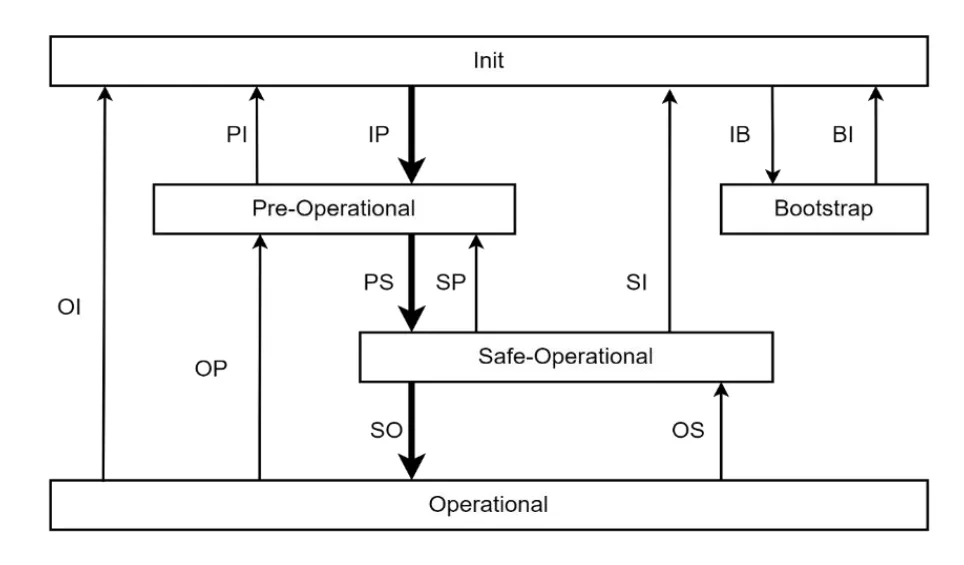
The node starts at Init and steps through Pre-Operational (mailbox communication and parameter configuration available), Safe-Operational (inputs are live while outputs stay in a safe state), and Operational (all inputs and outputs active); a Bootstrap state handles firmware updates. This staged unlocking ensures a configuration error never drives a motor directly.
Worth noting: through CoE (CANopen over EtherCAT), EtherCAT reuses CANopen's object dictionary, PDO/SDO mechanisms, and the CiA 402 servo drive profile — engineers familiar with CANopen migrate at very low cost.
These mechanisms give EtherCAT its exceptional synchronization, real-time performance, and flexibility, and make it common in humanoid robots, high-precision collaborative arms, CNC machines, and high-speed packaging lines, with up to 65,535 nodes per segment. The trade-off is higher cost and a higher development threshold than the other protocols.
The Four Protocols Side by Side
| Aspect | CAN | CANopen | CAN FD | EtherCAT |
|---|---|---|---|---|
| Role | Hardware bus (physical + data link layer) | Application-layer protocol on top of CAN | Bandwidth-upgraded CAN hardware protocol | Real-time Ethernet-based fieldbus |
| Payload per frame | 8 bytes | 8 bytes | 64 bytes | Standard Ethernet frame, far beyond the CAN family |
| Max bit rate | 1 Mbit/s | 1 Mbit/s | 1 Mbit/s arbitration, up to 5 Mbit/s data phase in practice | 100 Mbit/s full duplex |
| Multi-axis synchronization | No built-in mechanism | SYNC signal, limited accuracy | Better than CAN, still below EtherCAT | Distributed clocks, sub-microsecond jitter |
| Max nodes | Limited by bus load | 127 | Limited by bus load | 65,535 |
| Cost and development effort | Lowest | Low | Relatively low | Relatively high |
| Typical robot use | On-board component communication | Small multi-joint robots, simple service robots | Collaborative robots, lightweight humanoids | Humanoid robots, high-precision cobots, CNC machines |
In short: CAN is the four-decade hardware foundation; CANopen adds the standard language that lets devices interoperate; CAN FD fixes the bandwidth shortfall; and EtherCAT pushes synchronization into the microsecond range. The protocols are not ranked good to bad — each occupies its own performance and cost bracket.
Protocol Support in EYOU Products
EYOU's standard products cover CANopen, CAN FD, and EtherCAT:
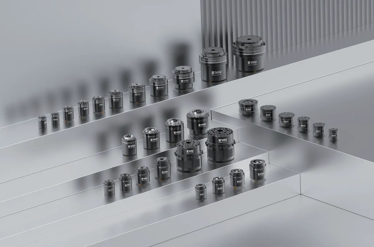
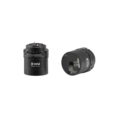
- The PHU enhanced harmonic actuators and RHU humanoid harmonic actuators support both CANopen and EtherCAT at the same frame size, switchable by software configuration for better system compatibility.
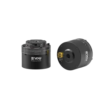
- The PHA lightweight harmonic actuators run CANopen on a CAN FD physical interface.
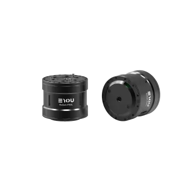
- The RP humanoid planetary actuators carry CANopen with a customizable CAN FD interface, delivering high-speed, high-bandwidth, low-latency real-time data exchange for demanding control scenarios.
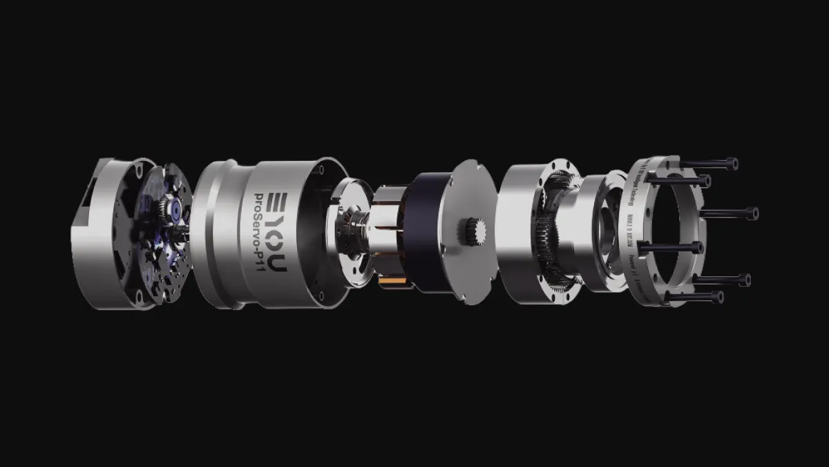
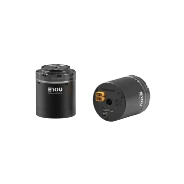
The model suffix states the protocol directly: C for CANopen/FD, E for EtherCAT, F for CAN FD, and R for RS485. For what sits inside a joint — motor, encoders, and drive — see What Is Inside a Robot Actuator. If you have a specific application question about matching a protocol to a joint, contact our application engineers directly.
FAQ
Three main differences: payload grows from 8 bytes to 64 bytes per frame; CAN FD uses a dual bit-rate mechanism that keeps the arbitration phase at the classic rate (up to 1 Mbit/s) for compatibility while the data phase runs faster, typically 5 Mbit/s in practice; and CRC checking is strengthened from 15 to 21 bits for better integrity on long frames. CAN FD is the bandwidth-upgraded version of CAN, standardized in ISO 11898-1 in 2015.
Only one way. A CAN FD node can send and receive classic CAN frames, but a classic CAN node cannot parse a CAN FD frame and will raise an error. On a mixed bus, CAN FD nodes must operate in classic CAN mode — 8-byte frames at no more than 1 Mbit/s.
Yes, with conditions. CAN FD nodes must switch to classic CAN-compatible mode, using 8-byte frames at no more than 1 Mbit/s, which suspends the bandwidth advantage. The dual bit rate and 64-byte frames are only available when every node on the bus supports CAN FD.
The core differences are the underlying architecture and synchronization accuracy. CANopen is an application-layer protocol on the CAN bus: 1 Mbit/s, 8-byte frames, at most 127 nodes, low cost and simple development. EtherCAT is Ethernet-based, using processing on the fly and distributed clocks: sub-microsecond synchronization jitter and up to 65,535 nodes per segment, at higher cost and development effort. Through CoE, EtherCAT reuses CANopen's object dictionary and the CiA 402 profile, so the application layer migrates smoothly.
Yes. EtherCAT runs at 100 Mbit/s full duplex versus CANopen's 1 Mbit/s, and its distributed clocks hold synchronization jitter below the microsecond level, while CANopen's SYNC mechanism is limited by CAN bus arbitration and bandwidth. But speed is not the only dimension — CANopen costs less and is simpler to develop, which remains the right answer where performance demands are modest.
The mainstream four are CAN, CANopen, CAN FD, and EtherCAT. CAN handles on-board component communication; CANopen serves small multi-joint and simple service robots; CAN FD balances bandwidth and cost in collaborative robots and some lightweight humanoids; and EtherCAT dominates wherever multi-axis synchronization demands are extreme, such as humanoid robots and high-precision collaborative arms. EYOU joint products cover CANopen, CAN FD, and EtherCAT, with the PHU/RHU series supporting software-switchable CANopen and EtherCAT at the same frame size.