FOC Control for Robot Actuators: How Field-Oriented Control Works
FOC control (field-oriented control, also called vector control) is a current control method for three-phase motors. It converts the stator currents into two components on axes that rotate with the rotor, one setting magnetic flux and one setting torque, and regulates the two separately. In a robot actuator, this makes motor torque roughly proportional to a single controlled current. This guide explains how the algorithm works, where it sits among the current, speed and position loops, how rotor position is obtained, and which datasheet figures describe the result, with EYOU PHU, RHU and RP actuators as examples. Here FOC refers only to motor control; the abbreviation also stands for terms such as free of charge in other fields.
What Is FOC Control?
K. Hasse at TU Darmstadt and F. Blaschke at Siemens pioneered vector control of AC motors from 1968 into the early 1970s (history of vector control). Today FOC is applied to permanent magnet synchronous motors (PMSM), brushless DC motors and AC induction motors.
The phase currents of a three-phase motor are AC signals whose frequency rises with speed. FOC measures them, transforms them into a frame that rotates with the rotor, and obtains values that appear as DC at steady state (MathWorks field-oriented control reference). A PI controller can hold a DC value without chasing a moving sine wave, so flux and torque are controlled in a way that resembles a separately excited DC motor.
The motor is one part of the larger system described in Robot Actuator Working Principle. FOC runs in the drive, between the motion command from the host controller and the power stage that switches current into the motor windings.
FOC vs Trapezoidal and Sine Wave Control
Brushless motors are commonly driven in three ways. They differ in what the controller regulates, and that sets the torque ripple and the sensing hardware required.
| Method | What is controlled | Torque ripple | Low-speed smoothness | Requirements |
|---|---|---|---|---|
| Trapezoidal (six-step) | Two conducting phases, switched six times per electrical cycle | Higher, with steps at commutation | Limited | Simple; Hall sensors are often sufficient |
| Sine wave | Phase currents following a sine reference | Lower | Good | Rotor angle; current lag grows with speed |
| FOC | Id and Iq in the rotating frame | Lowest of the three | Good, including near zero speed | Current sensing, rotor angle and coordinate transforms in each control cycle |
Robot actuators run at low output speed, start and stop often, and hold static loads. Torque ripple at the motor passes through the reducer and can appear as vibration at the end of an arm. Force and impedance control also depend on a torque that follows a command closely, and FOC supplies this through Iq. These needs outweigh the added computing and sensing cost in servo-grade actuators, which is why trapezoidal drive is used mainly where cost matters more than smooth torque.
How Field-Oriented Control Works
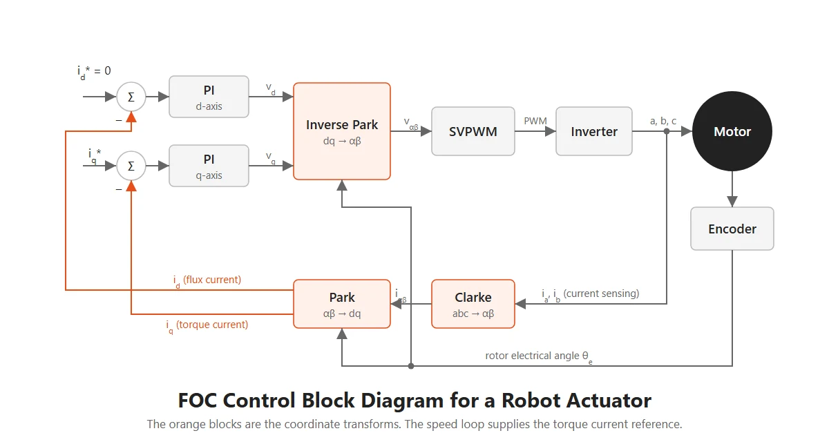
The FOC algorithm repeats the following sequence in each control cycle. The block diagram shows the signal path.
Measure phase currents and rotor angle
The drive samples the phase currents with shunt resistors or current sensors. In a balanced motor ia + ib + ic = 0, so two measurements are enough. The encoder gives the mechanical angle, and the electrical angle is θe = p·θm, where p is the number of pole pairs. The offset between encoder zero and rotor flux has to be calibrated: a 90° electrical error swaps the flux and torque axes, and a 180° error reverses torque.
Apply the Clarke and Park transforms
The Clarke transform maps three phase currents to two axes in a stationary frame:
iα = ia iβ = ia + 2ib√3
The Park transform then rotates those axes by the electrical angle, so that the d-axis aligns with rotor flux:
id = iαcosθe + iβsinθe iq = −iαsinθe + iβcosθe
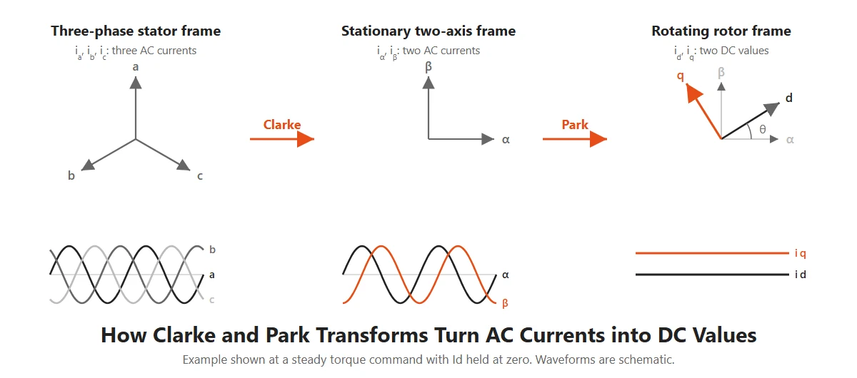
Id and Iq: flux current and torque current
Id produces flux along the rotor magnet axis, and Iq, at 90 electrical degrees, produces torque. The PMSM torque equation is:
Te = 32 p [ ψmiq + (Ld − Lq)idiq ]
where ψm is the magnet flux linkage and Ld, Lq are the d-axis and q-axis inductances. In a surface-mounted PMSM, Ld ≈ Lq and the equation reduces to:
Te ≈ 32 p ψmiq
Below base speed, the controller normally holds Id at zero, so all current produces torque. Above base speed, a negative Id weakens the flux and extends the speed range.
PI control, inverse Park and SVPWM
Two PI controllers compare the measured Id and Iq with their references and output the voltages vd and vq. An inverse Park transform converts these voltages back to the stationary frame, and space vector PWM (SVPWM) converts them into duty cycles for the six switches of the inverter.
Current, Speed and Position Loops in a Robot Actuator
FOC forms the innermost of three cascaded loops. The position loop outputs a speed reference, the speed loop outputs a current reference, and the current loop produces the motor voltage. Texas Instruments notes that the current loop has a strong influence on the bandwidth of the outer loops, and that delay from ADC conversion and algorithm execution limits current controller bandwidth to about a tenth of the sampling frequency (TI SPRT735).
On the EYOU PHU series, the current loop runs at 16 kHz and the speed and position loops at 8 kHz.
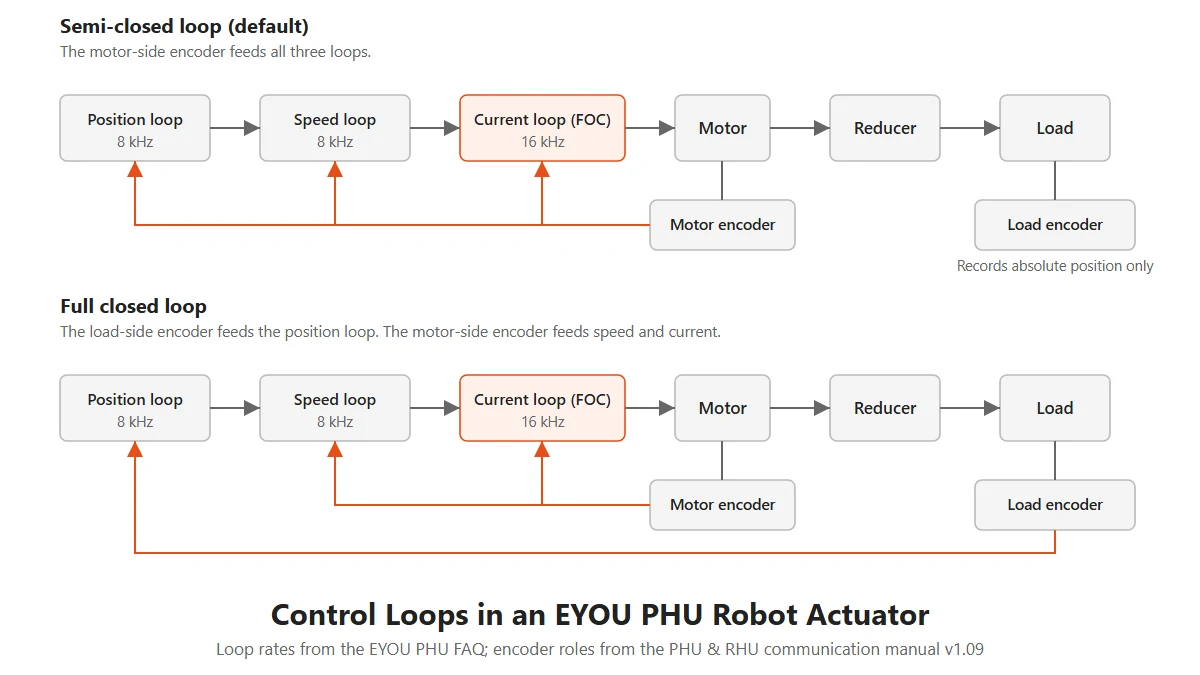
PHU and RHU actuators carry two encoders, and the communication manual defines two ways of using them:
- Semi-closed loop (default): the motor-side encoder handles position, speed and current loop calculations. The load-side encoder records the absolute position of the load.
- Full closed loop: the motor-side encoder handles the speed and current loops, and the load-side encoder handles the position loop.
The current loop stays on the motor side in both cases because the Park transform needs the rotor angle. Full closed loop lets the position loop measure the load directly, including reducer backlash and elastic wind-up. Robot Actuator Specifications Explained calculates this wind-up for a PHU actuator at rated torque.
A host controller can also close part of this structure itself. In cyclic synchronous velocity mode, the master plans the trajectory and the actuator runs its internal speed and torque loops. In MIT mode on RP actuators, a single command combines position, speed and feedforward current into the current reference:
iref = Kp(pdes − pact) + Kd(vdes − vact) + iff
This route is common on legged robots, where force control needs the current loop to respond directly to high-level commands. A study on proprioceptive actuators shows the same dependence: its FOC-based controller design treats torque and field control as the basis of high-bandwidth impedance control.
Rotor Position: Encoder or Sensorless FOC
FOC needs the rotor angle in each cycle. It can come from an encoder, a resolver or Hall sensors, or from a sensorless estimator that calculates the angle from voltage and current. Sensorless FOC removes a sensor and its cabling, but back-EMF based estimation has a known limit: maxon notes that the back-EMF signal is very weak at low speed and absent at standstill, and that holding position against an applied force is outside what this method can do (maxon on sensorless control). Methods based on magnetic anisotropy extend sensorless operation to standstill, with added complexity.
A robot actuator spends much of its time at low speed or holding a pose under load, so encoders remain the usual choice. PHU actuators use dual absolute encoders with 19 bits on both the motor side and the load side, or 524,288 counts per revolution. Absolute encoders keep position through a power cycle, so the actuator needs no homing after restart.
Running FOC on MCU, FPGA or SoC
The FOC algorithm can run as software on a microcontroller or as dedicated logic in hardware. The two differ in timing. On a typical MCU, a current sample waits for the calculation, and the result is applied at the next PWM update, which adds delay inside the loop. TI's fast current loop library reduces this latency to under a microsecond through careful partitioning across the processor's cores (TI SPRT735). An FPGA or a hardware FOC core runs the calculation in parallel logic, so sampling, calculation and update sit closer together and timing stays deterministic.
EYOU has moved through several hardware generations. The company developed a full-hardware FOC algorithm on FPGA, followed by dedicated proFOC chips with more than 100,000 cumulative deliveries, and SoC designs that integrate the MCU, FOC core and gate driver.
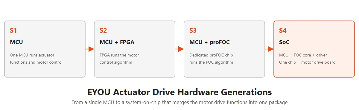
According to EYOU's product documentation, PHU and RHU actuators use an SoC design that reaches control performance comparable to the FPGA design, with a more compact structure and lower cost. RP actuators implement FOC in hardware with an FPGA.
What FOC Performance Means on an Actuator Datasheet
Several figures on a robot actuator datasheet relate to control speed, and they describe different things. The values below come from EYOU documentation:
| Figure | What it describes | EYOU example |
|---|---|---|
| Current loop frequency | How often the FOC current loop is executed | 16 kHz (PHU) |
| Speed and position loop frequency | Execution rate of the outer loops | 8 kHz (PHU) |
| Torque sensor sampling frequency | Update rate of the output torque measurement | 8 kHz (RHU-F) |
| Impedance control frequency | Execution rate of the impedance controller | 1 kHz (RHU-F) |
| Force control closed-loop bandwidth | Frequency range in which output torque follows a force command | 30 Hz (RHU-F) |
| Encoder resolution | Smallest angle the rotor angle feedback can distinguish | 19-bit dual absolute (PHU) |
A loop frequency and a closed-loop bandwidth should not be compared directly. Frequency states how often a calculation runs, while bandwidth states how fast the system responds, including the delays and the mechanics. When comparing actuators, ask which loop a figure refers to and under what load it was measured.
Control modes and bus timing also limit what the FOC loop can deliver. A multi-axis robot running cyclic synchronous modes over EtherCAT updates its targets once per bus cycle, and the current loop runs many times between updates. Robot Communication Protocols compares the bus options, and Robot Actuator Specifications Explained covers the rest of the datasheet.
FOC in EYOU Robot Actuators
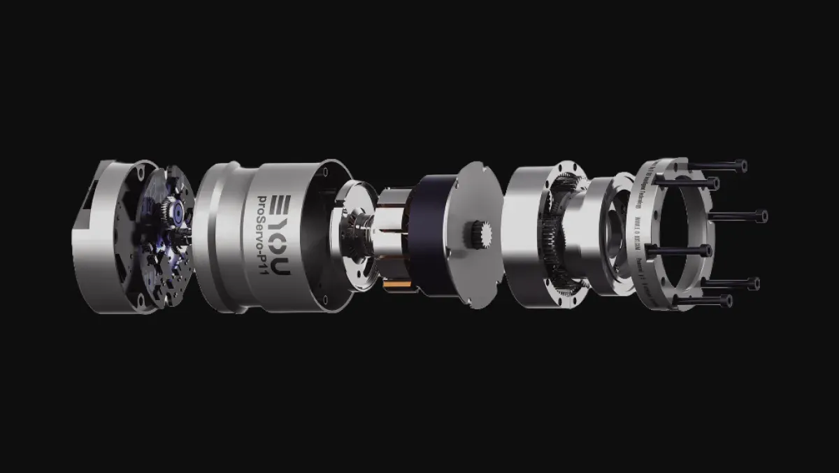
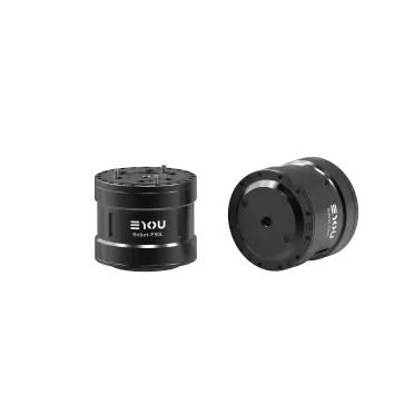
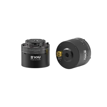
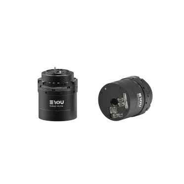
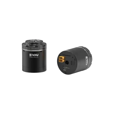
EYOU integrates the drive, FOC control and encoders inside each robot actuator, so the host controller sends position, speed or torque commands over the bus. The components are described in What Is Inside a Robot Actuator.
| Series | Reducer | FOC hardware | Encoder | Typical positions |
|---|---|---|---|---|
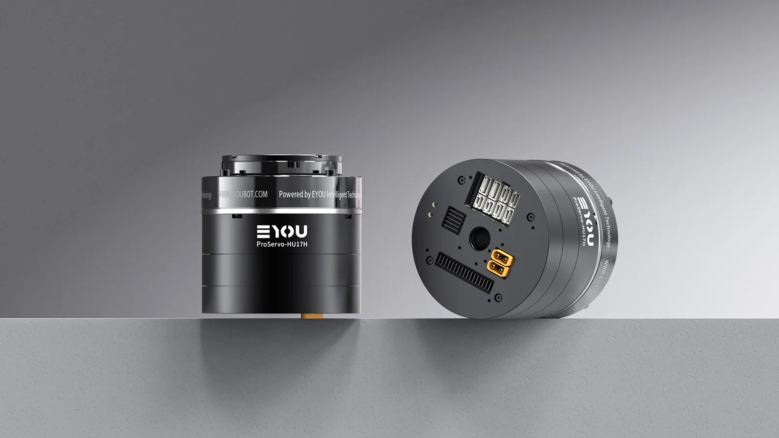
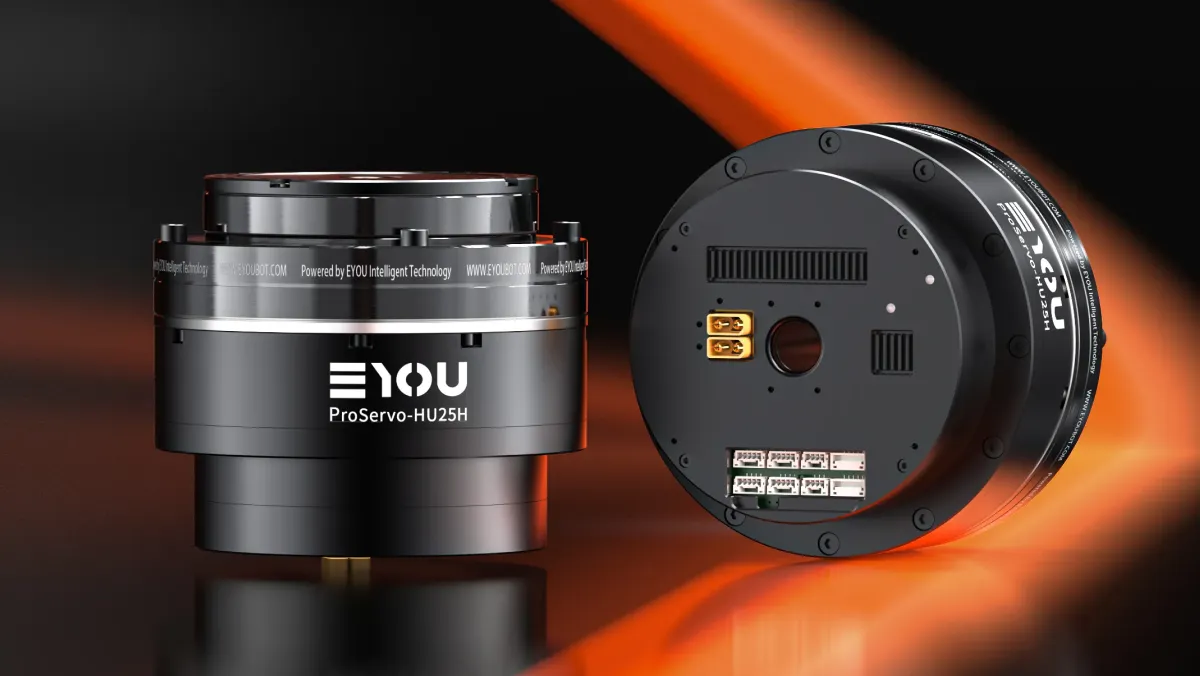
| PHU enhanced harmonic actuator | Harmonic | SoC | Dual absolute, 19-bit | Collaborative arms, humanoid upper body, industrial automation |
| RHU humanoid harmonic actuator | Harmonic | SoC | Dual absolute | High-precision humanoid positions |
| RP humanoid planetary actuator | Planetary | FPGA | Dual absolute | Humanoid legs |
Specifications and manuals for each series are available in the download center. If you are sizing an actuator for a control architecture that depends on current loop response or force control, send the joint position, load and control mode to our application engineers for a model recommendation.
FAQ
FOC stands for field-oriented control, also called vector control. It regulates a three-phase motor by converting its stator currents into a flux component and a torque component on axes that rotate with the rotor.
Trapezoidal control switches two conducting phases six times per electrical cycle. Sine wave control makes the phase currents follow a sine reference. FOC regulates Id and Iq in the rotating frame. Torque ripple falls in that order, and computing and sensing requirements rise.
FOC requires the rotor angle in each control cycle, from a sensor or an estimator. Encoders, resolvers and Hall sensors measure it directly, and sensorless methods estimate it from voltage and current. Robot actuators normally use encoders because they work at low speed and at standstill.
Id is the d-axis current, which produces flux along the rotor magnet axis. Iq is the q-axis current, which produces torque. In a surface-mounted PMSM below base speed, Id is normally held at zero and torque is approximately proportional to Iq.
Yes. FOC is commonly used on BLDC motors and PMSMs, and also on AC induction motors. It gives its smoothest result on motors with a sinusoidal back-EMF.
The current loop is the fastest loop in the drive. TI states that delay limits its bandwidth to about a tenth of the sampling frequency, so the required rate follows from the bandwidth the application needs. The EYOU PHU series runs its current loop at 16 kHz.
Hardware executes the FOC calculation in parallel logic, which reduces delay and keeps loop timing deterministic. Lower delay allows higher current loop bandwidth. EYOU uses FPGA designs, dedicated proFOC chips and SoC designs across its robot actuator series.
Sensorless FOC estimates the rotor angle from voltage and current, usually through back-EMF or an observer. Back-EMF is weak at low speed and absent at standstill, so pure back-EMF methods are unsuitable for holding position under load, a common requirement in robot actuators.